Automatic/ Semi Automatic Gauging System
Crankshaft Measuring and marking machine
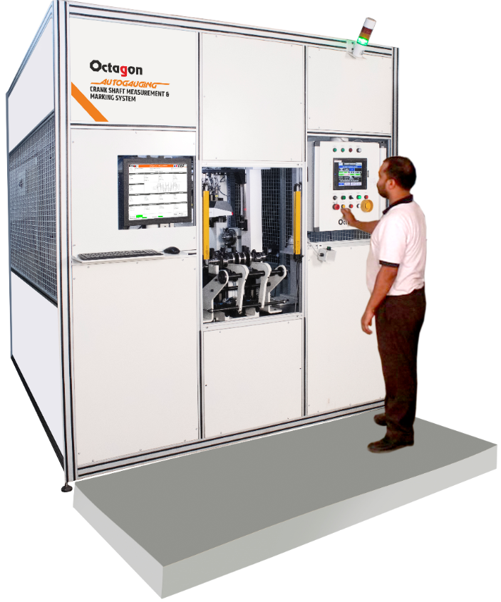
Measurement Parameters : Diameter and straightness & Roundness of various main journals and Pin journals including , Run-outs of various main journals w.r.t . Centre axis and end journal axis.
Total Measurement and analysis parameters : 88 ( Linear / Form and Geometry )
Cycle time ( Measurement + marking) : 65 Sec.
- Customised design for final inspection of crankshaft at production line – all parameter measurements in single rotation.
- PLC based fully automated cycle including loading / unloading, measurement and marking operations with assurance of highest safety POKA/YOKE.
- Use of high precision miniature contact type inductive probs facilitated measurement of each main journal and Pin journal ( width 22 mm) in 3 Sections.
- Measurement system consist of 70 Nos of High precision miniature inductive probes and a high resolution rotary encoder.
- High speed data acquisition system provided for dynamic and synchronised measurement of multiple Journals simultaneously.
- Powerful software for dynamic and synchronised data acquisition, processing of heavy data, strong mathematical algorithm for analysis of cam profile parameters,reporting , storage and data transfer .
- On-line thermal error corrections provided to ensure highly accurate measurements at ambient atmospheric conditions.
- Automatic gradation of every main journal in 3 grades each with 6 µm steps
- Automatic sorting of OK / NOT OK components.
- Data storage and sorting of measurement data of each component with unique identification and traceability of operator , date , time , Shift.
- Measurement cycle integrated with LASER marking machine for QR code marking on OK Components . Auto generated QR code
- Connectivity to the Local data server.Industry 4.0 Compliance
- Industry 4.0 Compliance
Cylinder Head Measuring and marking machine
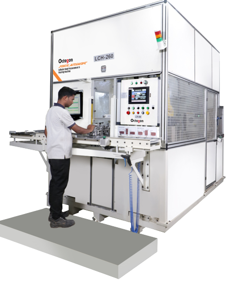
Measuring parameters: various Inlet & exhaust Cam bore diameters & ovality , various Valve Guide bore diameters, ovality & taper , Spark Plug bore diameters, ovality & taper.
Total Measurement and analysis parameters : 35 ( Linear / Form and Geometry )
Cycle time ( Measurement + marking) : 65 Sec.
- Customised design, fully automatic measuring and marking machine for final inspection of Cy. Head at production line .
- PLC based fully automated cycle including loading / unloading, measurement and marking operations with assurance of highest safety POKA/YOKE.
- Robotic automation ensure flexibility in applications – single machine used for measurement of 7 different models of cylinder heads (common machine for different 3 & 4 cylinder engines heads).
- Minimum cycle time is achieved with use of two robots working simultaneously, in synchronised operating mode.
- On loading of component, automatic model identification is provided with Camera based image processing software.
- Automatic selection of measurement program for different models.
- Measurement system consist of multiple air gauging tools – multi-jet air plug mandrels for cam bore, valve guide bore and spark plug bore. ( option available for measuring mandrels with contact type inductive probing system )
- Based on model identification, automatically right tool is selected from the tool library.
- Powerful software for synchronised data acquisition, processing, reporting, storage and data transfer to main server.
- On-line thermal error corrections provided to ensure highly accurate measurements at ambient atmospheric conditions.
- Measurement cycle integrated with LASER marking machine for QR code marking on OK Components . Auto generated QR code linked to Component number, model,date and time , shift and operator.
- Industry 4.0 Compliance
Camshaft Measuring and marking machine
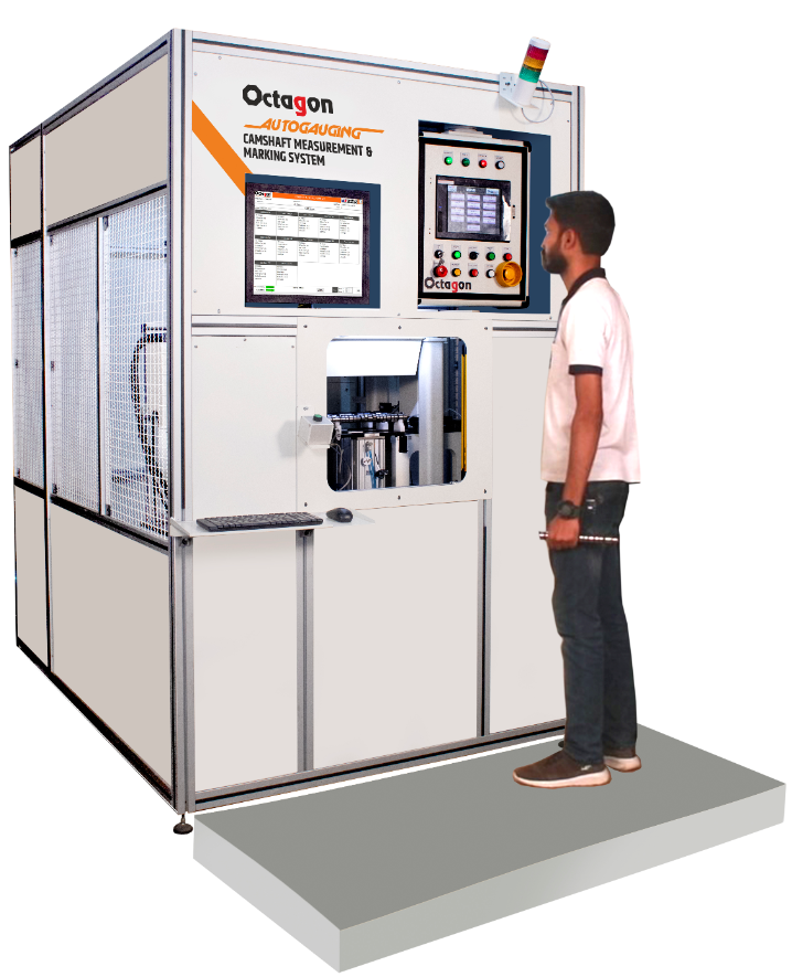
Measurement Parameters : Multiple Cam profiles -Lobe angles, lobe heights, lifts, Base circle dia, various journal diameters and forms, Run outs Etc. w.r.t . Centre axis as well as axis of end journals.
Total Measurement and analysis parameters : 149 ( Linear / Form and Geometry )
Cycle time ( Measurement + marking) : 58 Sec.
- Customised Design for final inspection of camshafts at production line – all parameter measurements in single rotation.
- Camshaft with 12 Cam lobes – measurement of all cam lobe profiles and 5 Journals simultaneously. ( in Single rotation) .
- PLC based fully automated cycle including loading / unloading, measurement and marking operations with assurance of highest safety POKA/YOKE.
- Measurement system consist of 24 Nos of High precision inductive probes 12 Nos. of linear encoders and high resolution rotary encoder.
- High speed data acquisition system for dynamic and synchronised data of multiple Cam lobes and number of Journals. ( in Single rotation)
- Powerful software for dynamic and synchronised data acquisition, processing of very heavy data, strong mathematical algorithm for analysis of cam profile parameters,
- reporting, storage and data transfer.
- On-line thermal error corrections provided to ensure highly accurate measurements at ambient atmospheric conditions.
- Automatic sorting of OK / NOT OK components.
- Data storage and sorting of measurement data of each component with unique identification and traceability of operator , date , time , Shift
- Connectivity to the Local data server.
- Industry 4.0 Compliance.
PLC Based Semi-Automatic Gauging System
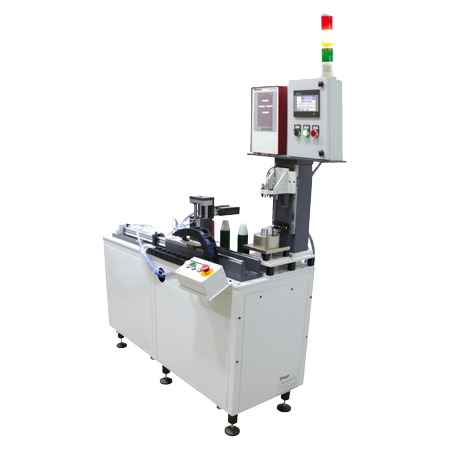
Technical Features :
- PLC/CNC controlled automatic / semi automatic measurement program which caters to emerging needs of Industry 4.0requirements.
- Measurement system offered with customised design suitable for measurement of multiple parameters in single operation.
- Offered with non-contact type air gauging, laser sensors or contact type precision inductive probes, or combination of air gauging + laser sensors + inductive sensors depending upon requirement.
- Computerised data processing for derived parameters and geometric feature derived by using 3D co-ordinate metrology software.
- Possibility to integrate with existing component handling line Gantry or line conveyor.Ability to communicate with the CNC machines, Robots, Gantry and Marking machines / Scanners simultaneously for complying the requirements of Industry 4.0.
- Can parallelly communicate to ioT softwares and SPC softwares for cloud computing.
- Standard shop floor applications for mass production of automobile or engineering parts like connecting rod, cylinder head, engine block, crank shaft, cam shaft etc.